In scientific research on software testing, you often come across papers filled with complex mathematical descriptions. Formal mathematics is commonly used in academia because it offers a precise way to describe how a system should behave in various situations, ensuring all possible cases are accounted for. However, for many testers, the math in these papers can feel overwhelming and difficult to apply to everyday testing work.
Terms like “Kripke structures,” “atomic propositions,” and “equivalence classes” might sound abstract and unfamiliar. However, these concepts aren’t as intimidating as they seem. They’re simply tools that help us think more systematically about a system, allowing us to create test cases that cover all the important behaviors.
In this post, we’re going to break down an example presented in Exhaustive Model-Based Equivalence Class Testing by W. Huang and J. Peleska, 2013. This paper provides a formal description of a ceiling speed monitoring function for a train. We’ll walk through the process of interpreting this formal description, the Kripke structure, understand each element of it including states, initial states, the transition relation, the labeling function, and most importantly the atomic propositions from which equivalence classes can be built to provide, under certain conditions, an exhaustive test suite—the ultimate goal for any tester.
Ceiling speed monitoring controller
The simple train control system we’ll discuss here is a Ceiling Speed Monitoring Controller, described in Exhaustive Model-Based Equivalence Class Testing by W. Huang and J. Peleska, 2013. This system, derived from the European Train Control System (ETCS), ensures that a train’s speed remains within safe limits by continuously comparing the train’s estimated speed () with a pre-set maximum speed, known as the Most Restrictive Speed Profile ().
The controller interface consists of the following inputs and outputs:

Diagram: Ceiling Speed Monitoring I/O Interface
| Interface | Type | Description |
|---|---|---|
| Input | Current speed estimation [km/h] | |
| Input | Applicable speed restriction [km/h] (MRSP = Most Restrictive Speed Profile) | |
| Output | Warning to train engine driver at driver machine interface (DMI) (1 = displayed, 0 = not displayed) | |
| Output | Emergency brake (1 = active, 0 = inactive) |
The system operates in three internal states , where (), as shown in the diagram below:
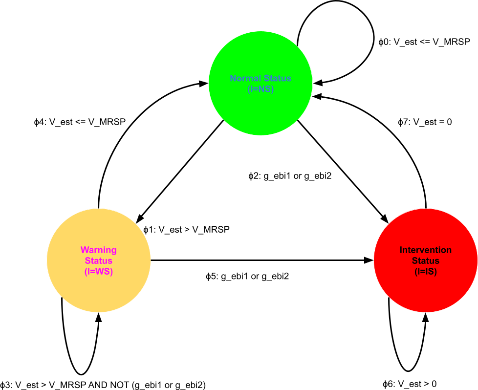
Diagram: Ceiling Speed Monitoring State Diagram
The guard conditions are defined as:
Here is the description of each state and threshold:
Normal Status (NS):
- When the train’s estimated speed is within or below the speed limit , the system remains in this state, and no warnings or emergency braking actions are triggered.
Warning Status (WS):
- This state doesn’t trigger the brakes but instead sends a warning signal to alert the driver. It’s like a speedometer alert that reminds the driver to slow down before reaching a more dangerous level.
- The Warning Threshold is when slightly exceeds but not by a critical margin.
Intervention Status (IS): When significantly exceeds , meeting conditions defined by specific guard thresholds, the system activates the emergency brake () to bring the train to a stop. The thresholds are specified by two guard conditions:
- Emergency Brake Activation Threshold for High Speeds ():
- Activated if and .
- This threshold is a safeguard for higher speeds, where even a small speed overage can quickly become dangerous. So, if the train exceeds 125 km/h where 110 km/h is the safe max, the brake kicks in to slow it down immediately.
- Emergency Brake Activation Threshold for Lower Speeds ():
- Activated if and .
- For lower maximum speed limits (110 km/h or below), the system is slightly more cautious. Here, if the train’s estimated speed exceeds the maximum by more than 7.5 km/h, the emergency brake (EB) is activated. This is because, at lower speeds, it’s easier to lose control if the limit is exceeded even by a small amount, so the threshold for triggering the brake is lower (7.5 km/h instead of 15 km/h). For instance, if the limit is 80 km/h, the brake will kick in if the train goes over 87.5 km/h.
Once the emergency brake is activated, it remains engaged until the train has come to a complete stop.
- Emergency Brake Activation Threshold for High Speeds ():
This layered approach helps avoid unnecessary braking while still maintaining safety, ensuring that the train operates within a safe speed range by alerting the driver early and only applying brakes when absolutely necessary.
What is a Kripke structure?
In the paper, the above system is formally described by a Kripke structure. While at first glance it might sound and look intimidating, we can learn to understand and use it effectively.
A Kripke structure is a formal model used to represent the behavior of a system in terms of its possible states and transitions between those states. Named after the logician Saul Kripke, this structure is widely used in fields like model checking, formal verification, and software testing, especially in systems where we want to ensure specific properties or safety conditions.
A Kripke structure is defined by , which is a tuple that contains the following elements (components):
States (): The different configurations that the system can be in. Each state represents a unique situation or condition within the system.
Initial States (): A subset of that contains the states in which the system can start. Initial states give the starting point(s) for evaluating the system’s behavior.
Transition Relation (): A relation that defines how the system can move from one state to another. Each pair in represents a transition from state to state , specifying the possible paths the system can take over time.
Labeling Function (): A function that maps each state to a set of atomic propositions that are true in that state. Atomic propositions describe properties or facts about the system (e.g., “speed exceeds limit” or “warning signal is on”).
Atomic Propositions (): The set of all atomic propositions. Atomic propositions are simple statements about the system that can be either true or false in each state. Again, they describe specific properties or conditions (e.g., “speed exceeds limit” or “emergency brake is active”) that help define what’s happening in any given state. The labeling function uses these atomic propositions to indicate which conditions hold true in each state, making it possible to analyze the system’s behavior based on these fundamental truths.
In summary, a Kripke structure captures the dynamics of a system by defining its states, how it can transition between states, and which conditions hold true in each state. This allows for systematic analysis of the system’s behavior and helps in verifying that it meets the system’s requirements or avoids unwanted conditions.
Let’s start unraveling what each element in the Kripke structure is as it applies to the Ceiling Speed Monitoring Controller.
The states
First, States () is the set of all possible states. But, what does an actual State look like? A State consists of input, internal (model), and output variables. In general, it could even include environment variables. It’s critical to understand that input and output variables are also part of the state!
In some cases, people think that the states of the system are only the circles seen in the state diagram. This is not the case. Those circles are just a part of the overall state description. In this case, the circles in the state diagram are represented as , where is an internal variable that can have values , corresponding to each status.
So, after including input, internal (model), and output variables in the state for the Ceiling Speed Monitoring Controller, its state is represented as a tuple:
Where:
- are input variables.
- is an internal (model) variable.
- are output variables.
The initial states
Second, we can choose by design that Initial States () for the controller are any states where (internal state is in Normal Status), (warning signal is off), and (emergency braking is off). Defining initial states helps provide a starting point for evaluating the system’s behavior and ensures consistency in testing from a known configuration.
This can be expressed mathematically as:
The above expression uses set-builder notation to define the initial states of the system in a formal way. Here’s a breakdown of each part of the expression:
: Represents the set of initial states for the system.
: Each element in is a tuple representing a specific initial state of the system, where:
- : Estimated speed of the train.
- : Maximum allowed speed.
- : The status of the system.
- : Warning signal status.
- : Emergency brake status.
Condition : This part specifies constraints for the elements in . It states that:
- must be equal to NS (Normal Status),
- must be `0` (warning signal is off),
- must be `0` (emergency brake is inactive).
In summary, this set-builder notation defines as the set of all possible initial configurations of the system where the system is in Normal Status (NS), the warning signal is off, and the emergency brake is inactive, while allowing and to vary.
The transition relation
The transition relation is one of the most important parts of the system description and provides a set of rules describing how the system shifts between states. In the paper, this transition relation is “specified by the predicate.”
“The transition relation is specified by the predicate.”
What does it mean “specified by a predicate”?
When they say that “the transition relation is specified by the predicate,” it means that a logical condition (or predicate) governs each possible transition. This predicate is an expression that, when true, allows a transition from one state to another. Each transition corresponds to a particular set of conditions that must be met for the system to change states.
How does it look like?
For the Ceiling Speed Monitoring Controller, is defined as:
This equation means that is true (i.e., a transition occurs) when at least one of the conditions through is true.
Where and , and the triple equal sign in formal logic and mathematics is used to indicate “definition” or “is defined as” which means that the left side is not just equal to the right side but is defined by it.
The symbol represents a disjunction (logical OR) of multiple conditions, indexed from to .
So:
- is the symbol for logical OR, indicating that at least one of the conditions must be true.
- to specifies the range of indices, meaning there are 8 conditions or predicates, labeled through .
- represents each individual predicate or condition in the set.
Thus, means that the expression is true if at least one of the predicates is true. We can be more explicit and rewrite it as:
The full transition relation
We can substitute the definitions into to get the final transition relation that fully defines how the internal (model) variable and output variables change in response to the current status and input variables.
At first glance, this expression may seem hard to understand. However, be patient, as we’ll break down what all of this means.
💡 It is important to note that the above expression defines a formula that describes the behavior of the system. This formula must hold for the system to operate correctly. Therefore, transition relations in finite-state systems can indeed be represented as mathematical formulas! This is very powerful and demonstrates that mathematics can model complex systems.
This idea of modeling systems as formulas can be found in TLA+. In TLA+, you describe a system’s behavior as a mathematical formula using temporal logic, which is a form of logic specifically designed for reasoning about time-dependent behavior.
Breaking down predicates (conditions)
Let’s break down each predicate (condition) in the definition of and see what it actually means.
Remember that each predicate specifies a condition for a possible transition. Here is the meaning of the basic logic symbols used in the predicates:
AND (): Both conditions connected by this symbol must be true for the overall expression to be true. For example, means that both the estimated speed exceeds the maximum speed and the system is in Normal Status (NS) for this condition to hold.
OR (): At least one of the conditions connected by this symbol must be true for the overall expression to be true. For instance, indicates that either the high-speed guard condition or the low-speed guard condition triggers.
NOT (): This symbol negates the following condition, meaning it’s true when the condition is false. For example, is true when the estimated speed is less than or equal to the maximum speed.
By understanding each predicate in , we gain insight into how the system behaves under different speed conditions and triggers appropriate responses like warnings or braking.
Here is the definition and explanation of each condition:
: Normal Status with Speed Below or Equal to Limit
- This condition states that if the system is in Normal Status (NS) and the estimated speed is within or below the speed limit , it remains in NS, with no changes to the warning signal or emergency brake .
: Transition from Normal Status to Warning Status
- When in NS, if the estimated speed exceeds the maximum speed , the system moves to Warning Status (WS) and activates the warning signal , with the emergency brake remaining unchanged.
: Transition from Normal Status to Intervention Status with Emergency Brake
- In NS, if the emergency braking conditions or are met, the system shifts to Intervention Status (IS), activates the warning , and applies the emergency brake .
: Warning Status with Speed Above Limit but No Emergency Brake Trigger
- When in WS and exceeds , but emergency braking is not triggered, the system stays in WS with and no change to .
: Transition from Warning Status to Normal Status
- If the system is in WS and returns to or below , it reverts to NS, turning off both the warning and emergency brake .
: Transition from Warning Status to Intervention Status
- In WS, if either or is satisfied, the system moves to IS and applies the emergency brake , with no change to the warning signal .
: Intervention Status with Speed Above Zero
- When in IS, as long as remains above zero, the system stays in IS, maintaining the warning and the emergency brake .
: Transition from Intervention Status to Normal Status at Complete Stop
- When in IS, if drops to zero, the system returns to NS, with both warning and emergency brake disengaged.
As we can see from the above descriptions, the math describes the correct behavior much more precisely and concisely than natural language. While it might seem confusing at first glance, once you get used to it, you will start to appreciate the elegance of formal mathematics.
The labeling function
With transition relations broken down into pieces, we now move on to the next element in the Kripke structure—the labeling function (). We know that the labeling function () maps each state to a set of atomic propositions that are true in that state. So the key here is to know what the set of atomic propositions are, and then this function will tell us which of those propositions will be true at a given state.
Mathematically, the concept of the labeling function is defined as:
As expected, this formula describes the labeling function , which assigns a set of atomic propositions that are true in each state. Here is how to read it and what it means:
The upside-down A symbol, written as , is a mathematical symbol that means “for all” or “for every.”
The crooked E written as is used in mathematics to denote “element of” or “belongs to.”
: This means “for all in .” Remember, is the set of all states in the system. This part of the expression indicates that the labeling function is defined for each state in .
: The labeling function applied to state returns a set of atomic propositions that hold true in that state. In other words, is the set of all propositions in (the set of atomic propositions) that are true in state .
: This is set-builder notation again. This set represents the set of all atomic propositions in for which is true. Here:
- : is an atomic proposition that belongs to the set of all atomic propositions .
- : This notation implies that holds (is true) in the state . So, is true if the proposition is valid in state . Note that we implicitly assume that has the value True. In other words, we don’t explicitly write because it’s understood that mentioning alone implies that is true in the given context. This simplification helps keep the math notation concise and avoids redundancy.
After breaking down the formula, we see that it states for each state in the system, the labeling function returns the set of all atomic propositions that are true in . This allows us to understand which properties or conditions hold in each state of the Kripke structure describing the system.
Because the labeling function depends on the atomic propositions, let’s move on and try to define what the actual atomic propositions are for the Ceiling Speed Monitoring Controller.
The atomic propositions
We’ve finally reached the atomic propositions which are grouped together in the set . But let’s define what these atomic propositions are and what they represent. What is an atomic proposition?
The term atomic proposition is commonly used in formal logic and system modeling to describe basic, indivisible statements that can be true or false in a given state of a system. It can be thought of as a basic condition. Here’s a breakdown of each word:
Atomic: The word “atomic” comes from the Greek word “atomos,” meaning “indivisible.” For system modeling, “atomic” means that the proposition is a fundamental, indivisible statement that cannot be broken down into smaller logical components. For example, “the train’s estimated speed is greater than the maximum allowed speed” is an atomic statement because it cannot be further simplified in the model.
Proposition: In logic, a proposition is a declarative statement that is either true or false. In the context of system modeling, a proposition represents a specific condition or property that can hold in a given state. For example, “emergency brake is active” could be a proposition that is true if the brake is on and false if it is off.
Therefore, an atomic proposition is a simple, indivisible statement that cannot be broken down further and cannot contain other logical operators such as (AND) or (OR), about a specific condition in the system that can be true or false.
Knowing the atomic propositions is critical for testing, and ideally, this would be the first question a tester asks before testing any system: What is the complete set of atomic propositions for the system?
The reason why knowing atomic propositions is critical to testing is that from them you can build equivalence classes that can provide exhaustive test coverage if the list of atomic propositions is itself exhaustive and matches the atomic propositions of the actual implementation.
This is the main point of the Exhaustive Model-Based Equivalence Class Testing by W. Huang and J. Peleska, 2013 paper, which shows that under certain conditions, exhaustive testing is possible using equivalence classes if the model of the system is known. Here’s a quote from the abstract:
“We prove that a finite collection of input traces whose elements have been selected from a specific set of input equivalence classes suffices to prove a conformance relation between the specification model and the system under test.”
For the Ceiling Speed Monitoring Controller, the paper states that the complete set of atomic propositions is:
But how do you build this list, or more precisely, this set? The answer is simple: You can get it from the transition relation specified as a predicate. Why? Because a predicate is a statement or function that contains variables and becomes a proposition when specific values are assigned to those variables.
“A predicate is a statement or function that contains variables and becomes a proposition when specific values are assigned to those variables.”
Here is again from which we can pull out the atomic propositions:
We also need the definitions of both guard conditions:
If we go through each predicate, we can list all the atomic propositions (conditions). Let’s go from top to bottom. For each , we’ll move from left to right and identify all unique propositions. Note that it might not be intuitive, but statements such as are propositions because they can evaluate to either true or false. How come? Because can be equal to the value or not. Each proposition will include one of the variables that are part of the state, which we know is described by a tuple that contains all input, model (internal), and output variables. Given that , we are looking for propositions related to variables.
Ok, let’s get started.
From we get:
We skip and because these propositions say that these variables will not change and nothing about what the actual values of these variables are. However, we know that the initial state has these variables set to , which means that the warning signal is off and emergency braking is off as well. Thus, we can add them as:
From we get:
Note we don’t repeat atomic propositions that we’ve already picked. We only look for the new ones. Therefore, because we already have , we don’t need to add it.
From we get:
Remember, because propositions are atomic, we took the definitions of and and broke them down into atomic parts:
From we get:
This is because we already have and . The by using De Morgan’s Law.
Thus, and , from which we get two new propositions.
From we don’t get anything new.
From we don’t get anything new either.
From we get:
Finally, from we get:
Now, let’s combine all these propositions into one set as follows:
But this does not match the expected:
This discrepancy arises because our set includes redundant propositions. The redundant propositions are those which are just negations or dependencies of other propositions. So, let’s go through our list and identify all the redundancies to match the expected result above.
Removing redundant propositions
Upon careful observation, we find the following redundant propositions:
- is redundant because . We assume the estimated speed cannot be negative, so is implicit and not necessary as an atomic proposition.
- is redundant because it’s just .
- is redundant because it’s simply .
- and are redundant as they are simply the negations of and , respectively.
- is redundant because it’s just , which can be simplified to the atomic proposition .
- is redundant because it’s simply , so we can simplify it to .
Removing these redundant propositions gives us the following set:
After removing all the crossed-out redundant propositions and rearranging the elements, we get the set of atomic propositions as stated in the paper:
With the set of atomic propositions in hand, we can easily create equivalence classes that can be used in testing as described in Using Atomic Propositions and Equivalence Classes (Part 1) and Using Atomic Propositions and Equivalence Classes (Part 2).
Conclusion
We’ve successfully decoded the formal description of a simple train control system, the Ceiling Speed Monitoring Controller, as described in Exhaustive Model-Based Equivalence Class Testing by W. Huang and J. Peleska, 2013. In the paper, the system was formally described using a Kripke structure. We’ve explored what a Kripke structure is, examined each component used to define it, and saw how it applies to the controller. We closely analyzed how a transition relation can be specified as a predicate—a mathematical formula—and how, from it, we can extract a set of atomic propositions that allow for the construction of equivalence classes to implement test cases.
When a complete list of atomic propositions is known for a given implementation, the set of test cases constructed from equivalence classes can result in an exhaustive test suite. This level of rigor is hard to achieve without a clear understanding and application of formal mathematics. While tackling formal definitions can be challenging at first, I hope this article, where I aimed to explain the math in as much detail as possible, will inspire more test engineers to embrace it. Formal concepts provide a strong foundation for thinking about systems we test in an abstract and structured way—a critical skill when testing real-world software systems.
